Electric Lighting
Once you have controlled, glare-free daylight in your building, you need to complement it with an electric lighting system that provides a work plane illuminance of 300 lux across all regularly occupied spaces and 150 lux in all circulation areas. The following workflow is also shown in this tutorial. You may also be interested in Solemma’s electric lighting tutorial series for Rhino and Grasshopper.
Task A: Select Luminaire
Pick a series of luminaires from a lighting manufacturer catalogue, download the IES file and provide a perspective, luminance intensity distribution and wattage of all luminaires that you end up using in your design. List those luminaires in a specification table (see Table 1).

Table 1: Example luminaire listing
Task B: Luminaire Placement
Select a representative space in your building and place the luminaires so that at least 300lux/150lux are maintained across all working/circulation areas (Figure 1).
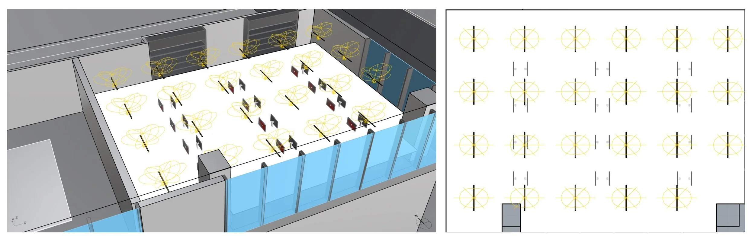
Figure 1: Illuminance distribution from electric lighting only
Task C: Visual Inspection in 3D
Explore different electric lighting designs by, for example, placing pendant luminaires at different heights off the ceiling. In Figure 2, the latter solution has fewer hot spots off the ceiling.

Figure 2: Scene visualization with different ceiling offsets
Task D: Lighting Power Density
Calculate the lighting power density for your space. The example space from Figure 1 measures 285m2 and is lit by 24 luminaires which each have a wattage of 28.1W. The resulting lighting power density (LPD) of the space corresponds to:
LPW = 24 x 28.1W /285m2 = 2.4W/m2
Tips:
For the electric lighting simulations make sure that your model units are in meter to match the IES-file dimensions.
You can limit your analysis to a representative part of your building. Do not place luminaires throughout your building as the simulation time currently scales linearly with the number of light sources in a scene.