HVAC - System Design
This advanced design exercise expands upon your initial HAVC design from the HVAC - System Selection and Layout assignment. You will quantitatively compare the energy performance of three HVAC systems for your project and layout the ductwork in three dimensions using the HVACer.gh grasshopper definition from the buildVAC GitHub repository. For the assignment, you will need a multi-zone thermal model of your design in ClimateStudio.
Task A: Performance Based Design
Up until this point, we have simulated different HAVC systems in ClimateStudio using an Ideal Air Load (IAL) system in EnergyPlus. IAL systems assume static coefficients of performance for heating and cooling without considering outside climatic conditions or varying hourly load demands. Real systems perform differently depending on how much heating or cooling they need to deliver at any given time step. The HVACer.gh grasshopper definition allows you to set up a detailed EnergyPlus simulation for three HVAC systems:
Variable Air Volume (VAV)
Fan Coil Units with Dedicated Outdoor Air System (DOAS)
Variable Refrigerant Flow (VRF) Heat Pump with DOAS
To support system selection, the definition reports estimated HVAC installation costs, operating cost, operation-related greenhouse gas (GHG) emissions and space requirements.
Getting started
To get started, open the ClimateStudio project in Rhino 3D. Please note that you have to setup your thermal model in grasshopper even if it is already defined in Rhino. In preparation for this, save any custom space use or construction templates in the thermal library of the Rhino file (see EUI Study - Envelope). The HVACer.gh definition supports up to two space use templates and one construction template. Thermal zones breps must be saved on a layer called “Thermal Zone 1/2.” Once your model is ready, open the HVACer.gh grasshopper definition and work your way through the steps outlined below.
Step 1 Define Location
Step 1: Define your weather file and ASHRAE climate zone for your project site
Figure 1: Select the weather file for your site (Search). Confirm it’s correct by checking the output.
Step 2 Define Emissions Factors and Utility Costs
Step 2: Define the emissions factors and utility prices for your location.
Figure 2: Edit emissions factors and utility costs for your location (Settings).
Step 3 Define Geometry and Template
To get started, select your main zone (and secondary zone, if any) Space Use template and save them as a new template in your Rhino file’s ClimateStudio library. Do this for your Construction template as well. As explained above, make sure your main zone geometry in the Rhino file is sunder a layer named THERMAL ZONE 1 and any secondary geometry under a layer named THERMAL ZONE 2. This way the components will recognize your geometry and bring them into the Grasshopper script.
Figure 3: Save the Space Use template and Construction template in Rhino, to the ClimateStudio library.
Step 4 Initiate Energy and Sizing Simulation
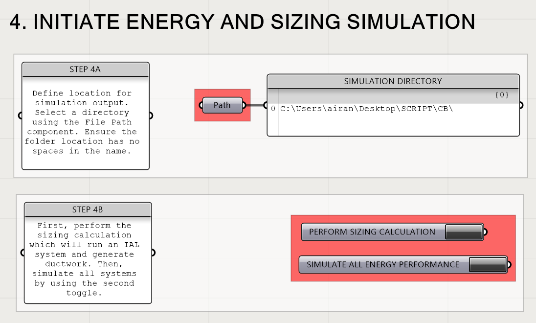
Step 4a: Specify a directory on your PC where you would like to save the simulation results. The path name should not include any blanks.
Step 4b: First, click Perform Sizing Calculation to run a quick, ideal air loads system energy model to generate ductwork. Then click, Simulate All Energy Performance to run an energy simulation for all three HVAC systems.
Figure 7: Select a simulation directory and perform sizing calculations.
Task B: Spatial Design
In this portion of the exercise, you will design the spatial layout of your selected HVAC system by going through the Spatial Design portion of the HVACer.gh definition. Follow the steps below to modify the geometry of the HVAC system based on spatial and aesthetic considerations.
Step 1 HVAC Spatial Layout
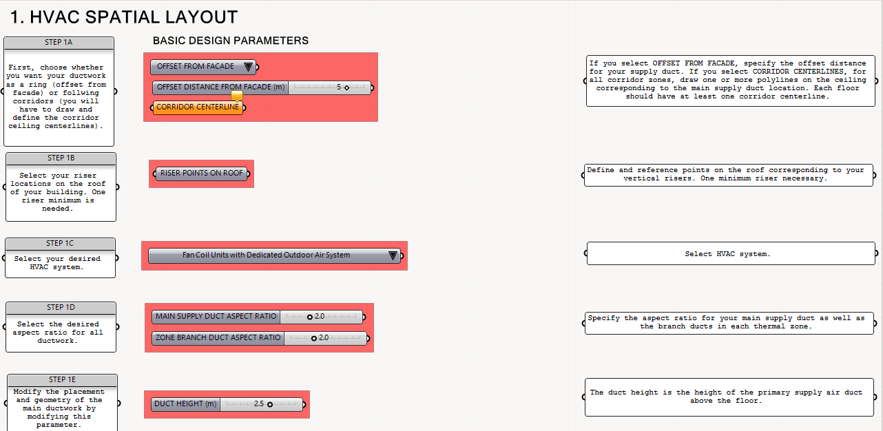
Step 1a: Select whether you want your main air distribution ducts to be drawn offset from the facade or to follow the path of a corridor centerline. By default, the facade offset method is selected and you need to specify the distance the duct is offset from the perimeter edge of the building. If you select the corridor centerline method, you will need to draw a polyline in the ceiling of every corridor zone and select this geometry in Grasshopper.
Step 1b: Draw and select riser points on the roof of your building. You need a minimum of one riser. Selec
Step 1c: Select your desired HVAC system from the dropdown menu and assign the points for your risers. You an modify the riser position by moving the base point along the roof surface.
Step 1d: Select the desired aspect ratio for your ductwork.
Step 1e: Modify the placement and geometry of the main ductwork vertically.
A summary of the various geometric parameters is provided in the Grasshopper script. Consider placing risers near core locations or toward the back of of the building and route the primary supply air ducts through circulation areas.
Figure 10: Preview and bake Grasshopper geometry in Rhino. The image on the right shows the output three-dimensional duct geometry.
Once you have completed your initial design in Grasshopper, bake the various elements in Rhino. You can access the different geometries using the various Preview components in the script (Figure 10). Right-click on each component and then bake the corresponding geometry to a Rhino layer.
For your selected HVAC system, provide an axonometric view of your building with the ductwork and equipment generated by the design tool. Refer to a sample drawing in Figure 11.
Then take your building section drawing from the previous exercise and now add central plant and any terminal equipment such as boilers, chillers, cooling towers, air handling units, as well as fan coil and VRF units. Label all equipment and show how they connect (i.e. hot water pipe, chilled water pipe, refrigerant line, air duct). You can use the outputs of the tool as a starting point for your drawing. Be sure your ducts do not conflict with interior partitions or structure. Refer to Figure 12.
In addition, you will then then draw a plan view of a typical floor showing the location of your vertical risers and the horizontal ducts on the floor. Provide a source of air for each one of your thermal zones. Be sure your ducts do not conflict with interior partitions or structure. You previously determined the size for the vertical shaft and can now approximate the dimensions of the horizontal ducts as well. Label key dimensions on the floorplan. You can use the outputs of the tool as a starting point for your drawing. Refer to Figure 13.
Submit section and floorplan drawings , axonometric view and system justification as a single PDF document.
Figure 11: Axonometric view of building with variable refrigerant flow (VRF) units and a dedicated outside air system (DOAS). Key equipment on the roof/basement, risers, and terminal equipment in each zone are indicated. Credits: Ashutosh Lohana and Yanyi Liu.
After your energy model has finished running, you should see a detailed energy use breakdown for the above listed HVAC systems along with a series of additional performance metrics for evaluation. An example output is shown in Figure 8. The figure shows that the all-electric VRF with DOAS system has the lowest operational energy use and required floor area along with the highest first cost. Given the performance metrics from the table as well as your general knowledge of and preference for HVAC systems, indicate which system you select going forward. Submit a screenshots of your version of Figure 8 and a brief motivation for your system choice.
Figure 8: Energy use breakdown and performance metrics for all three HVAC systems.
Figure 12: Section view of three story office building. The building has a fan coil unit (FCU) system with dedicated outside air (DOAS). The drawing indicates the supply air and return air ducts and shafts, their dimensions, as well as the location of the air handling unit, cooling tower, boiler, and individual fan coil units in each space.
Figure 13: Plan view of a typical floor showing HVAC risers (supply and return) and main horizontal ductwork, along with branches to each thermal zone.
Figure 9: Spatial layout settings in the Grasshopper script.
Once you have completed your initial design in Grasshopper, bake the various elements in Rhino. You can access the different geometries using the various Preview components in the script (Figure 10). Right-click on each component and then bake the corresponding geometry to a Rhino layer.
Related Video Tutorial/Handbook Chapter
MIT SDL buildVAC GitHub repository
Step 3a: Select whether your building is an office or apartment building using the dropdown option. Then select your main zone Space Use template and the Space Use template for any secondary zone types (if any). If your layers are named correctly, your geometry will be automatically added to the script.
Figure 4: Select your building program. Select the Space Use template for your main thermal zone and any secondary zones (Select). The two pipeline components will import your geometry if they are under the layer name THERMAL ZONE 1 (main zone) and THERMAL ZONE 2 (additional zones).
Step 3b: Select the Construction template for your entire building.
Figure 5: Select your Construction template (Select).
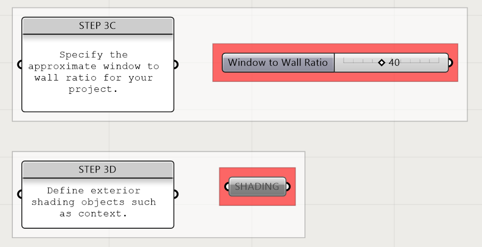
Step 3c: Define window to wall ratio and shading.
Figure 6: Define an approximate window to wall ratio for your project and select any shading elements, which should be modeled as single surfaces.


