HVAC - System Selection and Layout
At this point you should have set up a multi-zone thermal model of your project, reduced electric lighting and space conditioning loads and determined ventilation requirements for a minimum outside air (DOAS) or all-air (VAV) system. In this exercise, you will first select a HVAC system (Task A) and then place individual components within your design (Task B).
Task A: System Selection
Go through the HVAC System Selector webform and select an HVAC system for your building. Key choices include the air distribution type (natural ventilation, all-air or minimum outside air), any terminal systems (fan coil or variable refrigerant flow units), and central plant equipment (boiler, chiller, cooling tower, etc.). Provide a screenshot of your chosen HVAC system (or the closest option) and justify choice including - for example - space savings, energy efficiency, or other metrics.
Please note, if you intend to work through the advanced HVAC - System Design exercise, you may skip Task B.
Task B: Spatial Design (basic)
Update Section
Based on your system section from Task A, pick the relevant air distribution section from HVAC - Ventilation Requirements exercise and add the central plant and any terminal equipment such as boilers, chillers, cooling towers, air handling units, as well as fan coil and VRF units. Label all equipment and show how they connect (i.e. hot water pipe, chilled water pipe, refrigerant line, air duct). Use the webform section from Task A as a reference. Make sure that your ducts do not conflict with any interior partitions or structural elements. An Adobe Illustrator file with HVAC components can be found here.
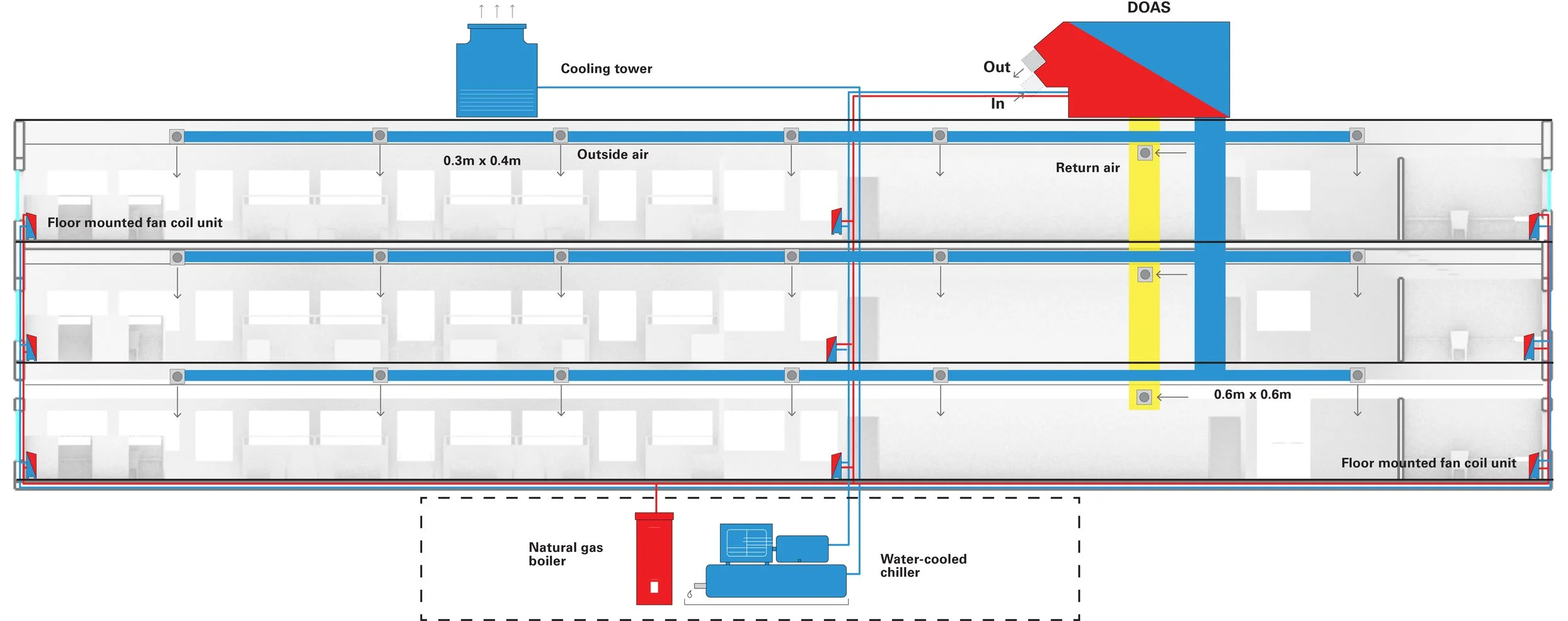
Determine the size of the horizontal air ducts on every floor based on the previously determined vertical air shaft size. Assuming constant air requirements throughout the building, the cross section for each horizontal floor duct corresponds to serviced floor area divided by the total conditioned floor area and multiplied by the vertical air shaft area. E.g., for the example building below, the vertical shaft area is 0.6 x 0.6 m2 and so the main horizontal duct on each of the three floors is 0.3 x 0.4m2.
Figure 2: Section view of a three story office building. The building has a fan coil unit (FCU) system with dedicated outside air system (DOAS). The drawing shows supply air and return air ducts and shafts, their dimensions, as well as the location of the air handling unit, cooling tower, boiler, and individual fan coil units on each space.
Typical Floorplan
Draw a representative floor plan that shows the location and dimension of the vertical risers and the horizontal ducts. Include the position of fresh air terminals for each thermal zone and avoid any conflicts with interior partitions or structure.
Figure 3: Plan view of a typical floor showing HVAC risers (supply and return) and main horizontal ductwork, along with branches to each thermal zone.
Submit section and plan drawings along with a brief system description as a single PDF document.
Related Video Tutorial/Handbook Chapter
MIT SDL buildVAC GitHub repository


